Q : What is the operating system for the OTDR?
A: The operating system for the OTDR is Windows CE
Q: What Modules can be added for the OTDR.
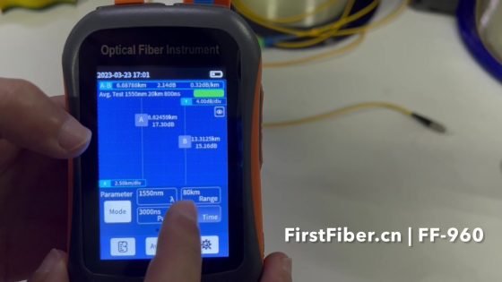
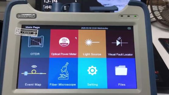
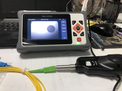
A: The OTDR supports power meter module, light source module, micro scope module, able to add touch screen feature.
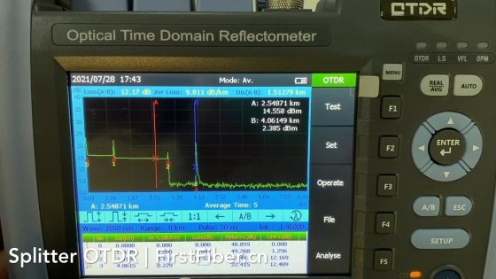
Q: What Pulse width should use when testing the fiber
A: The key is to always use the shortest pulse width possible that will satisfy the trace quality and allow the user to see the end of the fiber. Short pulse widths are used for short fibers. Long PW’s are used on long fibers. If the trace quality exhibits excessive noise that cannot be removed by additional averages, select the next higher pulse width.
For the OTDR, please refer to the table below:
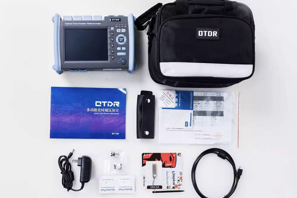
Q: What Adapters included by OTDR
A: The standard fiber adapter for the OTDR is FC, SC and ST. LC is for options.
Q: How to test a bare fiber
A: It is recommended to use a pigtail and mechanical splicer to test the bare fiber. Connect a pigtail of the correct fiber type and connector to the OTDR or far end of a launch cable. Cleave the opposite end of the pigtail and insert it into a mechanical splice. Cleave the end of your fiber to be tested and insert it into the opposite side of the mechanical splice. By using the “Real Time” function available on most OTDRs you can adjust the position of the fibers in the mechanical splice to get the best throughput. The cable is now ready to be scanned.

Comments are closed.