
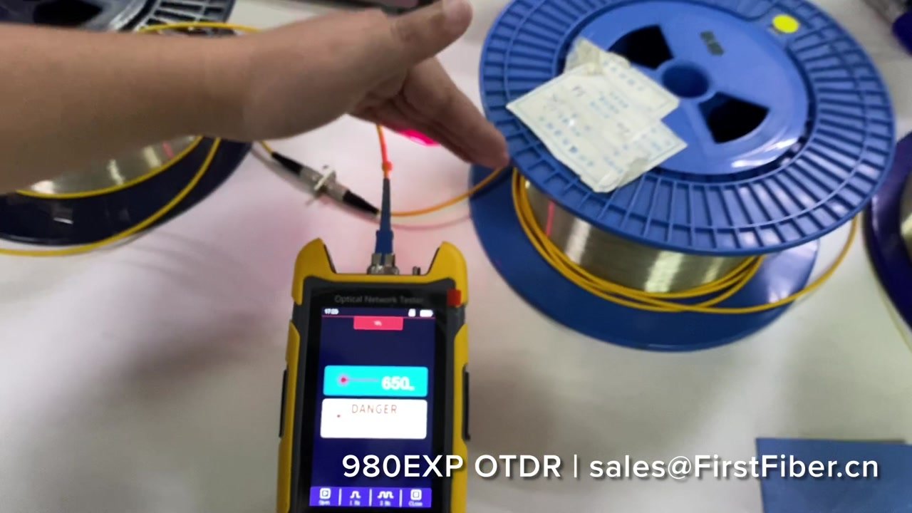
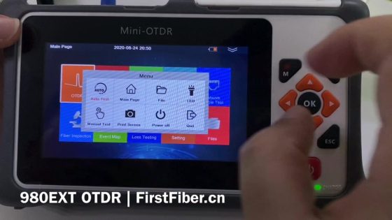
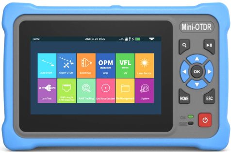
What is OTDR?
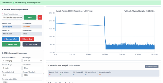
The optical time domain reflectometer (OTDR) sends a series of light bursts into the optical fiber for processing test. The way to test is to receive the light signal on the same side of the incoming, because the incoming signal will scatter and reflect back when it encounters a medium of different refractive indexes. The back scattering signal is measured along with time, so it can be converted to the length of the fiber.
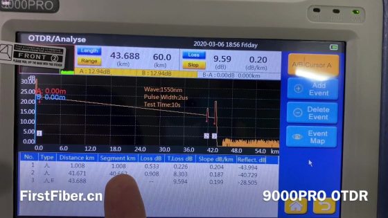
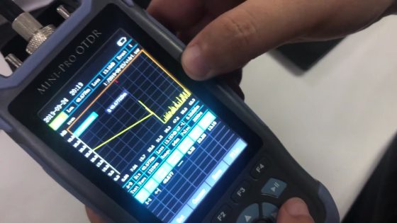
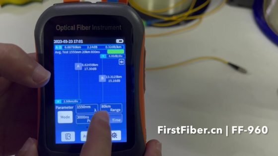
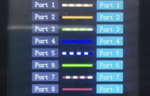
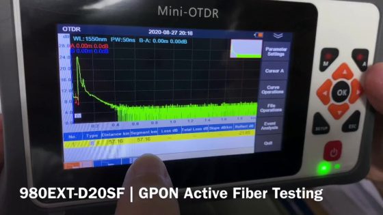
The OTDR can be used to measure the length and attenuation of optical fibers, including fusion splicing point and mechanical connectors . It can also be used to measure the breakpoint when the fiber is broken.
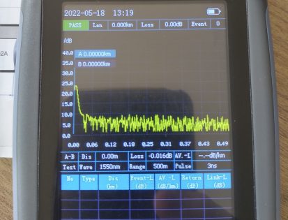
The difference between the size of the OTDR dynamic range and the DB at the low noise level is defined as the dynamic range of the OTDR. Wherein, the initial point of the backscatter level is the level value of the incident light signal, while the noise low level is the backscatter signal is the invisible signal. The size of the dynamic range determines the distance of the OTDR measurable fiber. When the level of the backscattered signal is lower than the OTDR noise, it becomes an invisible signal.
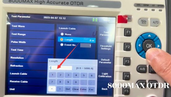
With the development of optical fiber splicing technology, people can control the loss of optical fiber connectors below 0.1DB, in order to effectively observe all small loss fiber connectors of the entire optical fiber, people need large dynamic range OTDR. There are two main ways to increase the OTDR dynamic range: increasing the initial backscatter level and reducing the noise low level. The factor that affects the initial backscatter level is the pulse width of the light. The factor that affects the noise level is the average scan time. Most models of OTDR allow the user to select the light pulse width parameter injected into the fiber under test. In the case of the same amplitude, a wider pulse produces a larger reflected signal, that is, a higher backscatter level, that is, the larger the width of the light pulse, the greater the dynamic range of the OTDR.
The OTDR repeatedly sends pulses to the fiber under test and averages the curve of each scan to obtain the resulting curve, so that the random noise of the receiver is suppressed as the average time increases. The display curve of the OTDR shows that the noise level decreases with the average time, so the dynamic range increases with the average time. The improvement in dynamic range performance is significant over the initial average time, significant improvement in dynamic range performance over the next average time, and gradually slows down over the next average time, that is, the longer the average time, the greater the dynamic range of the OTDR.
If you use a single-mode OTDR module to measure a multimode fiber, or use a multimode OTDR module to measure a single-mode fiber such as a single-mode fiber with a core diameter of 62.5mm, the measurement results of the fiber length will not be affected, but the results such as fiber loss, optical joint loss, and return loss are incorrect. This is because when the light is incident from the small core diameter fiber to the large core diameter fiber, the large core diameter cannot be completely filled by the incident light, so it causes errors in the loss measurement, so when measuring the fiber, it is necessary to choose the OTDR that matches the fiber under test for measurement, so as to get the correct results of each performance index


Comments are closed.